iss_dedu Type: Disk Drive Exerciser and Disk Head Alignment Tool

Supported drive models: ISS/Sperry Univac 8420 and 8430 drives, possibly others

Power Supply: DEDU-externally provided

Year of production: 1979

ISS P/N: 9025389-00

Dimensions:

Weight:

Story:

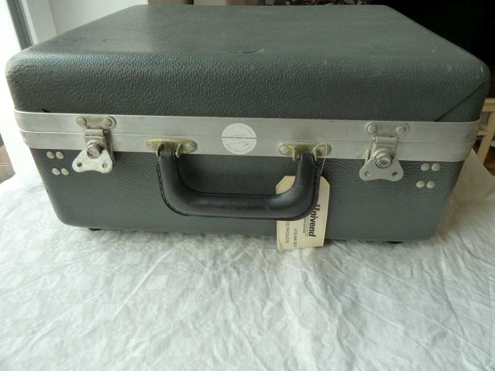
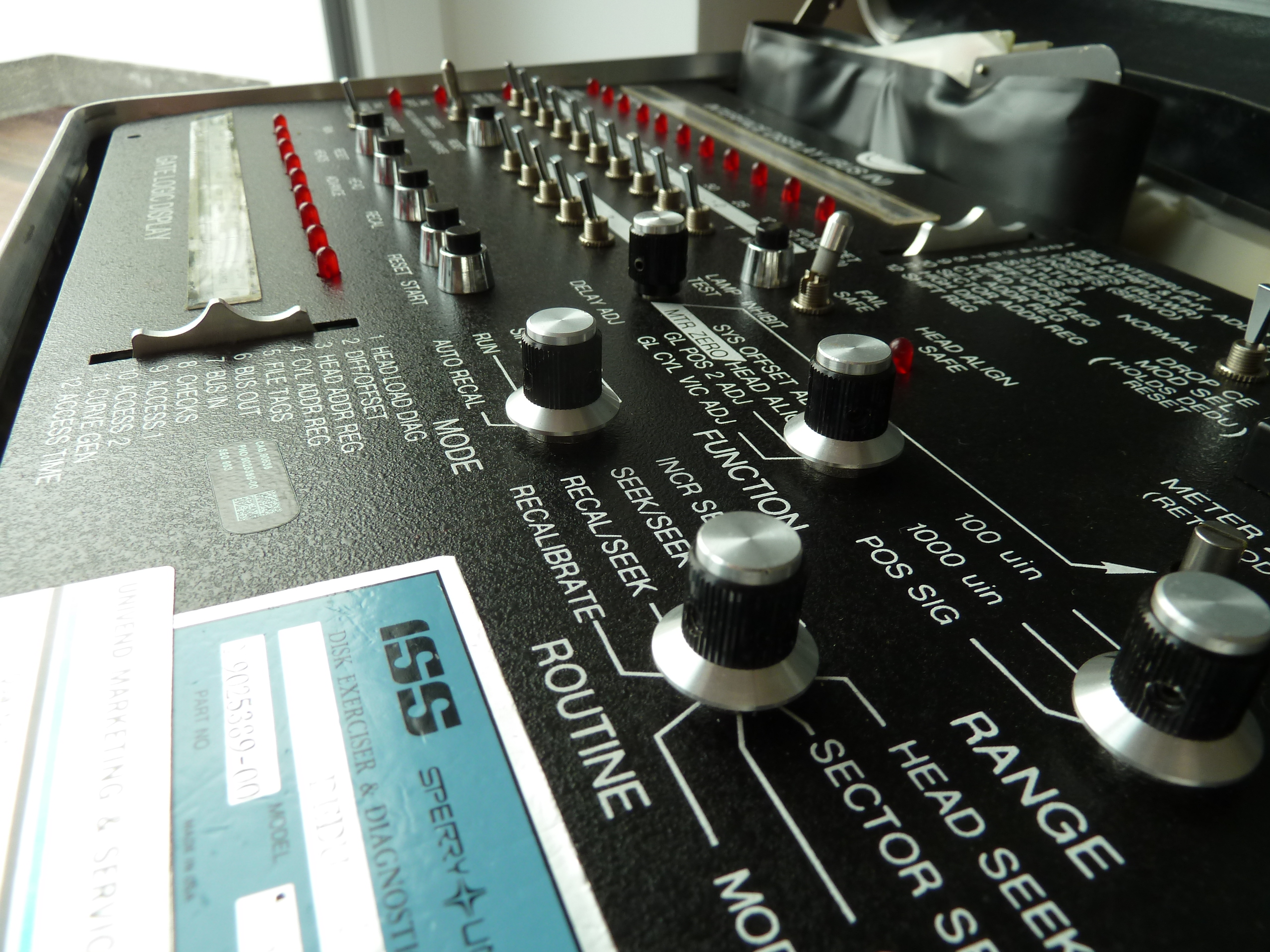
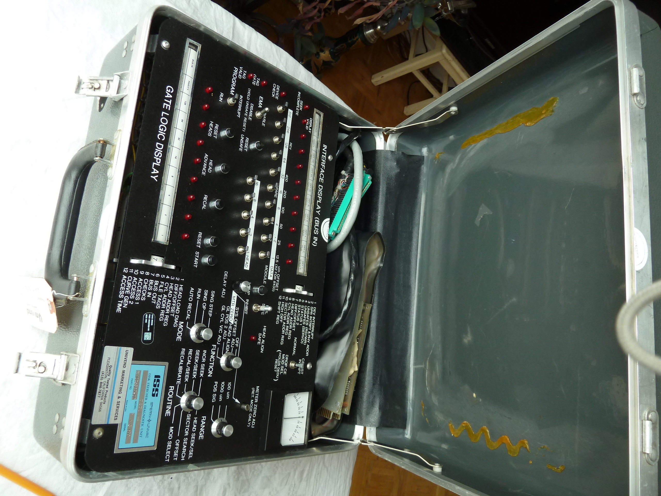
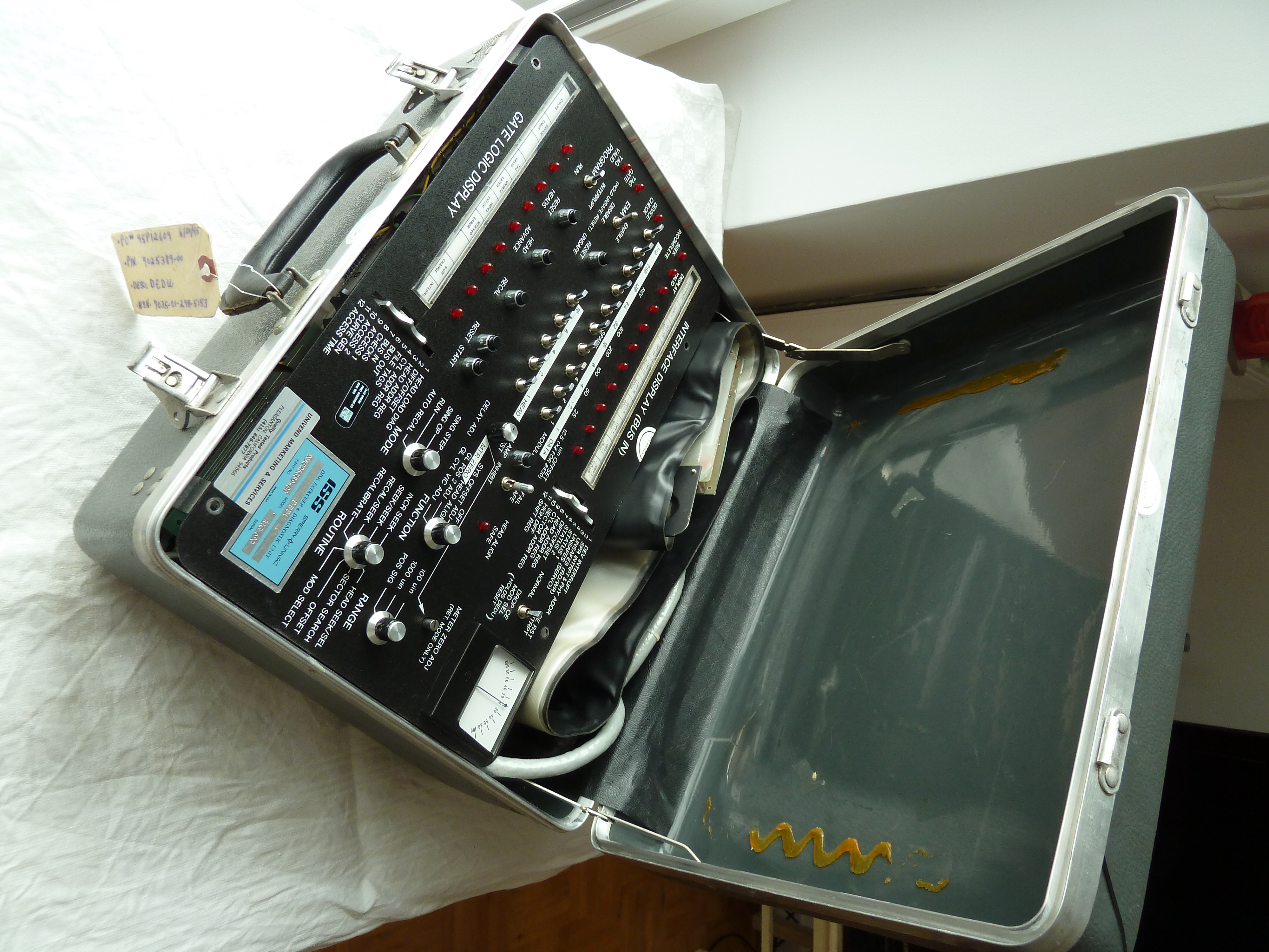
This disk drive exerciser joined the collection via ebay from 
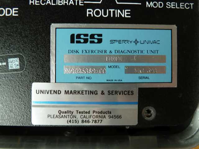
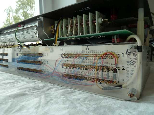
USA. It was designed by Information Storage Systems ( ISS ) and most date codes found on internal cables and boards 
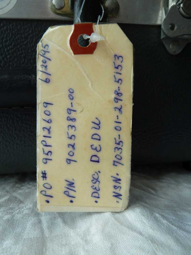
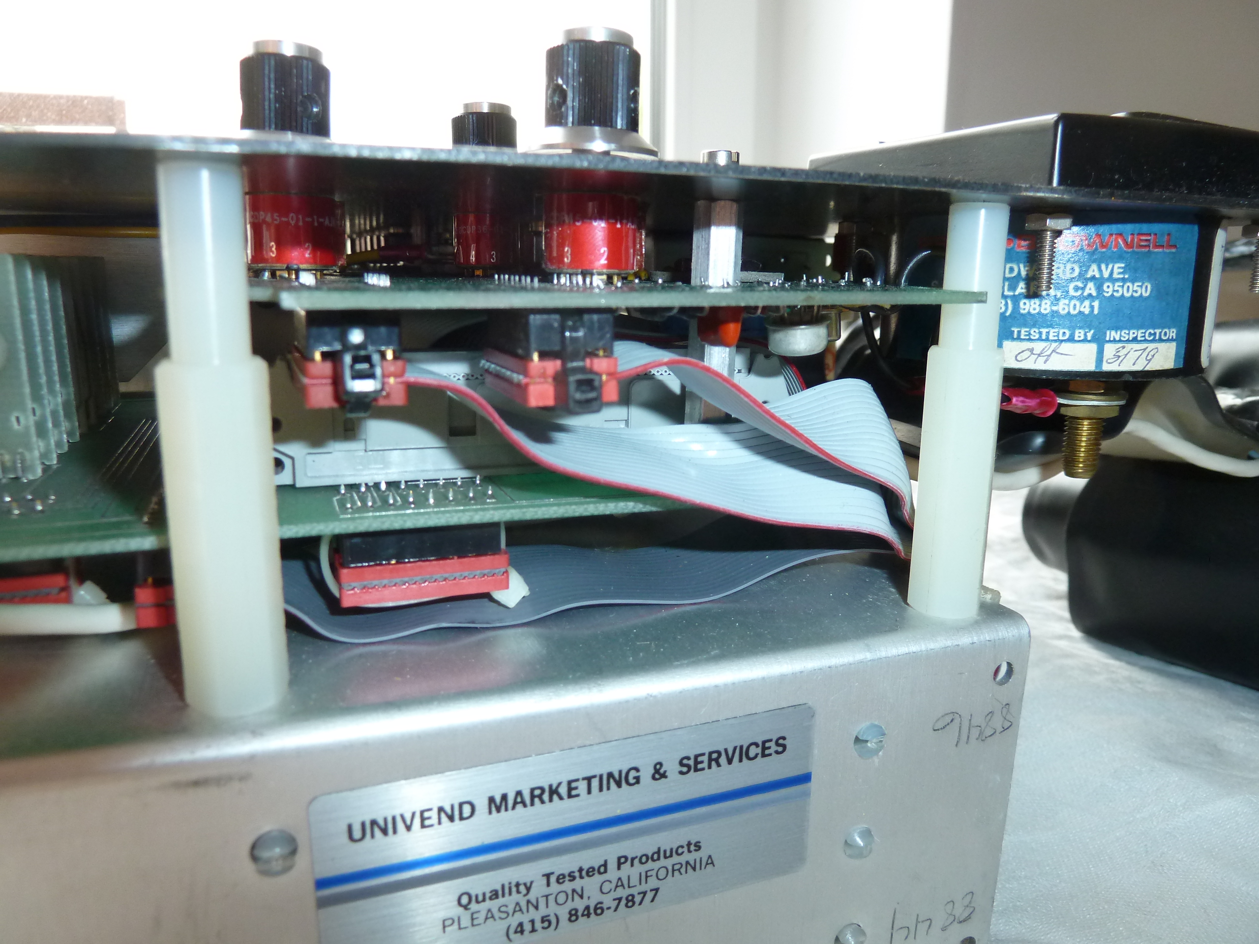
indicate that this unit dates from the year 1979. A label attached to the case includes "1995" as a date.
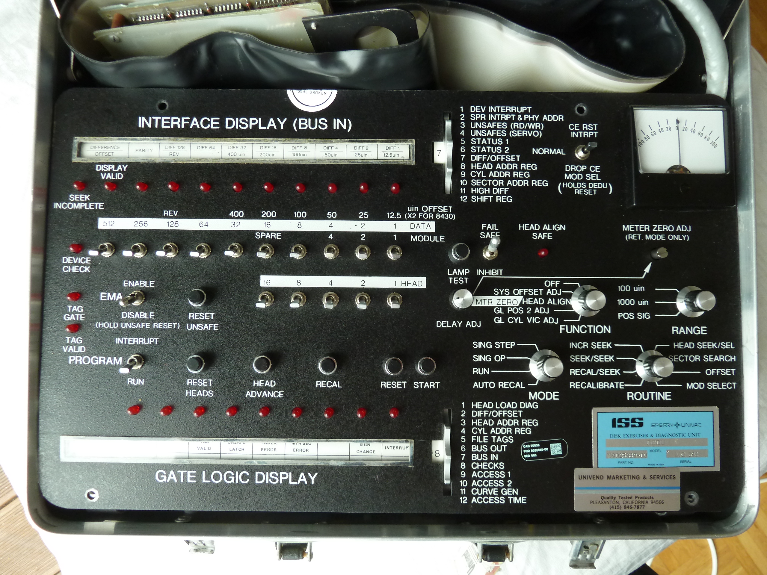
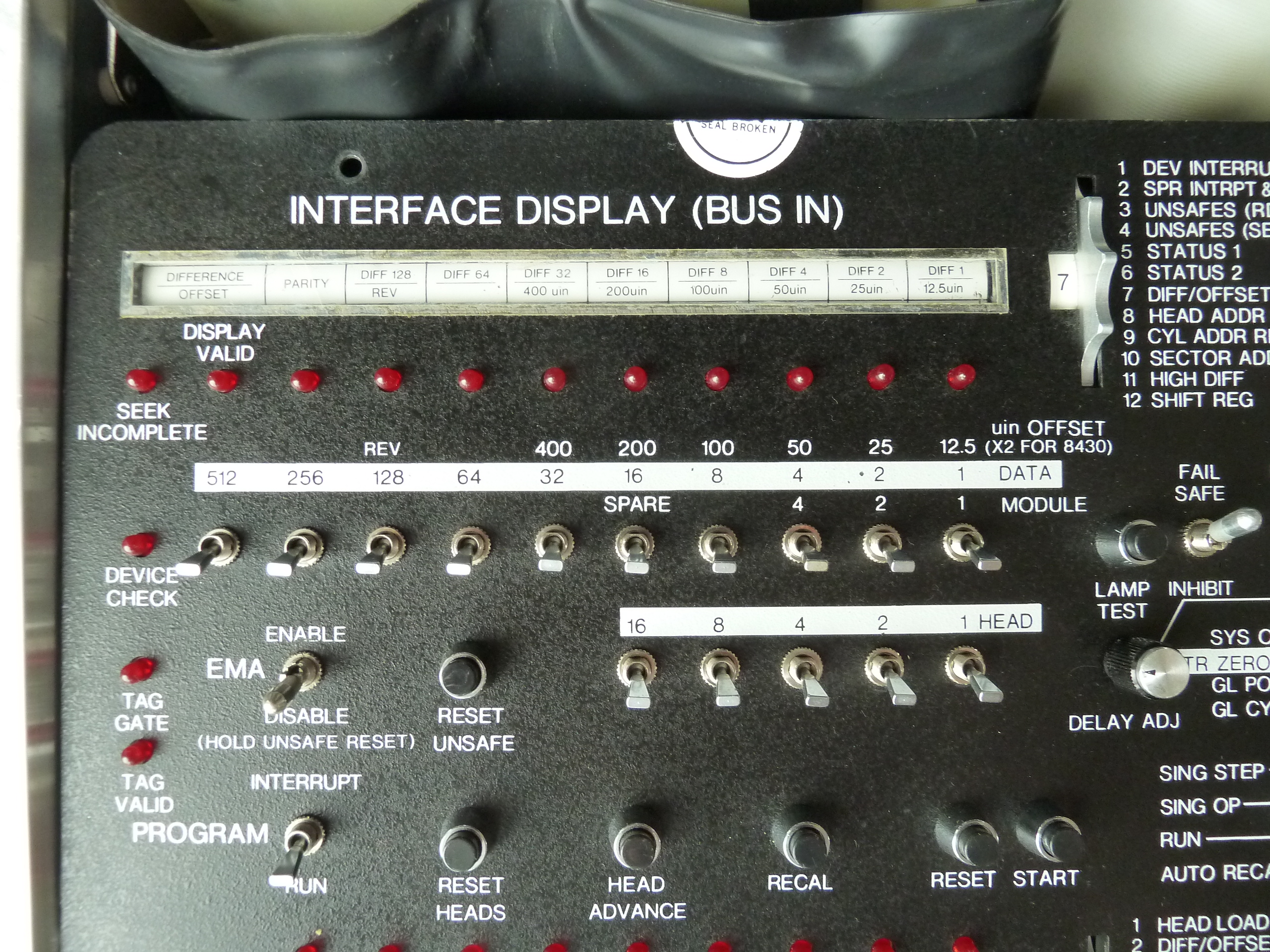
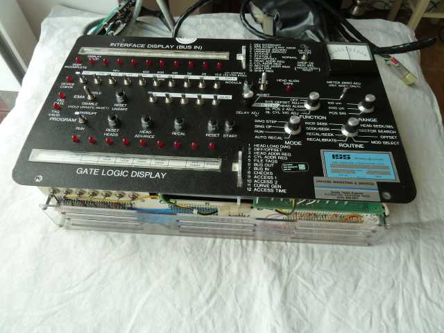
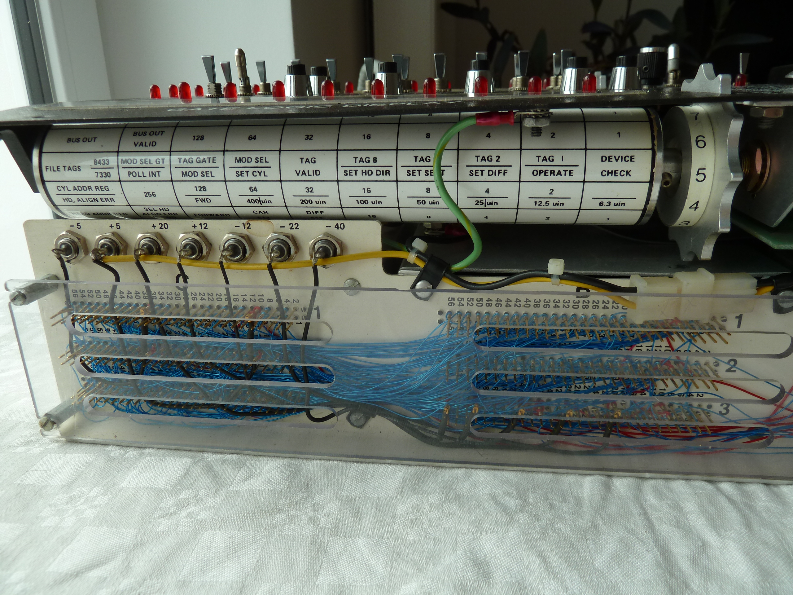
The implementation of the ISS exerciser is very different compared to the exercisers made by Control Data (the latter called them "Field Test Units", or in short FTU). The functions of the ISS exerciser are chosen via rotary switches, whereas exercisers such as the TB216 from Control Data offers a keyboard in addition to switches to choose the desired test routines.
As this unit came without any documentation, and as I couldn't find anything about it on the web so far, my knowledge about this exerciser is currently very limited. Particularly the disk drive models supported by this exerciser would be of great interest to me!

If anybody has more information about this, please drop me a short note! I'd be very grateful about it.


More pictures of the ISS Disk Exerciser:


closed case
Left: The disk exerciser well-protected in the transportation case. When there was the need for servicing disk drives,  field engineers would arrive with such a case to the customer's site where the disk drives were located.

Right: Overview of the entire operator panel. Click on the image for a high-resolution version.
panel overview
ISS-label
Left: ISS label on the operator panel.

Right: The label attached to the case. It contains different part numbers.
closed case
interface-display-section
Interface Display section of the DEDU on the left, Gate Logic Display section on the right.
gate-logic-section
interface-display-section: function select
Interface Display section of the DEDU on the left, Gate Logic Display section on the right.
gate-logic-section: function select
interface-display-section: choices
Left side: Close-up of the menu chosen available a particular function that is provided by the rotary switch for the interfae display section.

Right side: Side view of the nicely arranged operator panel.
Panel-pic
operator panel
                      from the side
Views from the side that visualize the nice finish of the operator panel. Click on the pictures for higher-resolution pictures. Panel-pic
disk drive connector #1
One of the connectors to the disk drive under test has a switch in order to set its capacity: 200MB or 300MB. switch at disk
                      drive connector #1
disk drive connector #1
Left: The three other connectors are displayed: One for power, two more for drive- and receive-signals.

Right: Driver- and receiver-signal connectors.

switch at disk drive connector #1
disk drive connector #1 Left: Close-up of the power connector. The disk exerciser is supplied by an external power possibly supplied by the disk drive itself.

Right: Top-view of the driver- and receiver-connectors.
switch at disk drive connector #1
disk drive connector #1 Left: The disk exerciser taken out of the protective case.

Right: The unit contains several logic boards which are interconnected via a wire-wrapped backplane.
switch at disk drive connector #1
operator panel
                      from the side
Left: Here, the panel of one of te two rotary switches is visible. It basically consists of a long non-hollow (!) cylinder made of aluminium.

Right: the connector side of the rotary switch: It is made from nine small electrical rotary switches which are all synchronized using a long rod.
Panel-pic
operator panel
                      from the side
Left: The different voltages used for power supply are visible. There are some odd ones amongst them such ass +20V, -22V and -40V. The wire-wrapped backplane is carefully protected by a transparent plastic cover.

Right: Side-view of the operator panel which allows to see the mounting of the potentiometers and switches.
Panel-pic
operator panel
                      from the side
Left: Data cabling interface to the disk exerciser.

Right: The rotary switch of the bus interface menu.
Panel-pic
Panel-pic
The disk exerciser is equipped with several logic boards all labelled "ISS".
Again the disk exerciser and diagnostic unit placed in the protective case with the disk drive interface cables and the power supply cable at the back.
Panel-pic